The 'Glow' circuit assembly
| Site: | ΕΛ/ΛΑΚ Moodle |
| Course: | 3D printing with circuits and Arduino |
| Book: | The 'Glow' circuit assembly |
| Printed by: | Guest user |
| Date: | Monday, 6 October 2025, 6:01 PM |
Description
Assemble a simple, pre-made circuit with light that you can incorporate into your 3D designs.
1. Introduction
In this tutorial, you'll learn how to build light up 3D designs using the Glow Circuit Assembly, which combines a light emitting diode (LED) and a coin cell battery. It's a simple way to incorporate a bit of light into your Tinkercad designs. We provide the 3D model for the circuit holder and cutout, and you incorporate it into infinite glowing fun!

You'll need 3D printing tools, a pair of wire cutters, and two electronic components:
- An LED (shown is 10mm). It is an electronic component that emits light when activated.
- A 3V Coin Cell Battery (CR2032)
IMPORTANT: Coin cell batteries can cause serious injury if swallowed. Keep coin cell batteries out of reach of small children!
2. 3D print the Glow holder
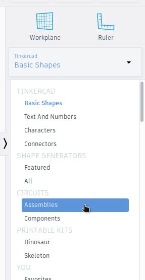
Open up a new 3D design in Tinkercad, then
click the Shapes panel dropdown and select Circuit Assemblies from the
list.
Move a Glow holder to the workplane. You'll notice that scaling is locked, so you can't resize it. This restriction is in place because specific, real life, electronic components need to fit into the holder.

Export the holder as a .STL file to prepare for printing. When you import the Glow holder onto the Tinkercad workplane, illustrations of the electrical components are shown, but will not export/print along with the holder. They are there only so you can see where the components sit in the holder.

Now it's time to 3D print your parts! The recommended settings are 20% infill with raft enabled, with supports disabled.
3. Trim the LED legs
Notice that one leg of the LED is longer than the other. This is to indicate which pin is positive and which one is negative. The longer pin is positive (+) and will correspond with '+' side of the coin battery used to power the LED.
The
length of the pins as they come are too long to fit into the Glow
assembly. Use the wire cutters to snip off the shorter negative (-) pin
so that it's about 1.5cm long. and the longer positive (+) a bit longer.

4. Add the coin cell battery

Pick up your coincell CR2032 battery, and align the positive side
(labelled "+") with the “+” indicator on the printed holder. Once
inserted, the battery interacts with the two small grooves to create
spaces just the right side for the leads of an LED, sandwiching them
together.
5. Add the LED & Glow!

Insert the LED from the top, making sure that the longer (positive) leg lines up with the “+” indicator on the holder.
Gently push the LED all the way in until the bottom of the plastic 'bulb' sits flush with the top of the holder.
Your LED should now light up!
If it is not lighting up, try flipping it around. Make sure that your battery and LED are inserted in the correct direction aligned with the “+” on the holder.
To turn off your glow assembly, remove the LED.

Material and images adapted from the Build the Glow Circuit Assembly Instructable authored by Tinkercad.