Infinite* colours
2. Pulse width modulation
So how does PWM work? Imagine turning the lights on and then off in your room. The room looks bright for a moment, and then dark again. If you continue to flip the light switch back and forth at a slow rate, the room just appears to be bright, then dark, over and over.
But something strange happens when you flip the light switch faster and faster. Rather than just appearing bright followed by dark, your room will have a light level somewhere in between bright and dark. In fact, the room will also appear brighter if you leave the light on for slightly more time than you leave it off. Your room will have a light level that is the average brightness that is dependent on the percentage of time that the light is on in relation to the percentage of time the light is off.
PWM uses a technique similar to flipping the light switch to create a brighter or dimmer light level. When you use PWM on the Arduino, the level of voltage on the PWM pin is switched on and off at various rates at regular intervals. It is sometimes 0 volts, and sometimes 5 volts.
Pulse Width Modulation, or PWM, is a technique for getting analog results with digital means. Digital control is used to create a square wave, a signal switched between on and off. This on-off pattern can simulate voltages in between full on (5 Volts) and off (0 Volts) by changing the portion of the time the signal spends on versus the time that the signal spends off. The duration of "on time" is called the pulse width. To get varying analog values, you change, or modulate, that pulse width. If you repeat this on-off pattern fast enough with an LED for example, the result is as if the signal is a steady voltage between 0 and 5v controlling the brightness of the LED.
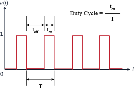
By varying the amount of time the pin is turned on and off, the Arduino creates an average voltage value between 0 and 5V.

Not all digital pins can be used with PWM. The ones that can are marked by he ~ symbol on the Arduino: pins 3, 5, 6, 9, 10, 11.
analogWrite() is function that can be used with these pins to output a variable amount of power with PWM. We will use it to control brightness levels of the appropriate LEDs.